Two parallel strips made from 9.5 cm wide 3 mm thick aluminum were glued and screwed to the tops of the main central arches on both sides reaching in front and behind just beyond the limits of the sliding window cover (main hatch). These would provide a smooth, rigid and rust-free surface for the roller bearings to glide upon.
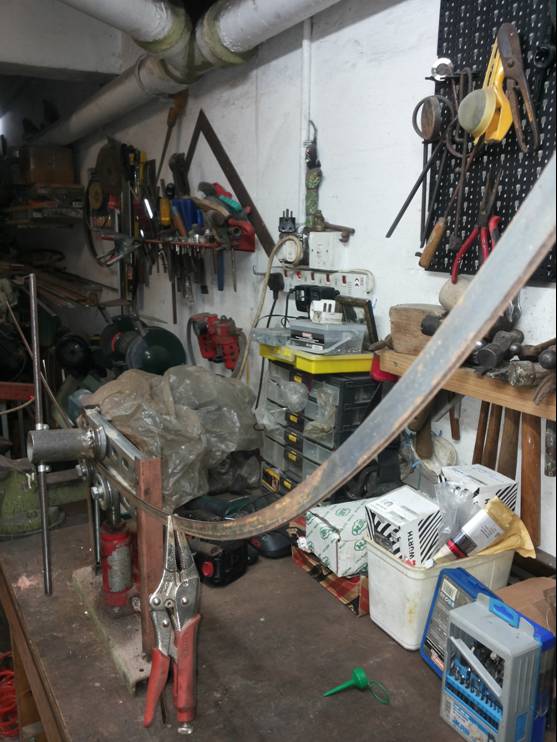
Dummy test runners were used for trying out the width and extent of motion of the projected shutter door.

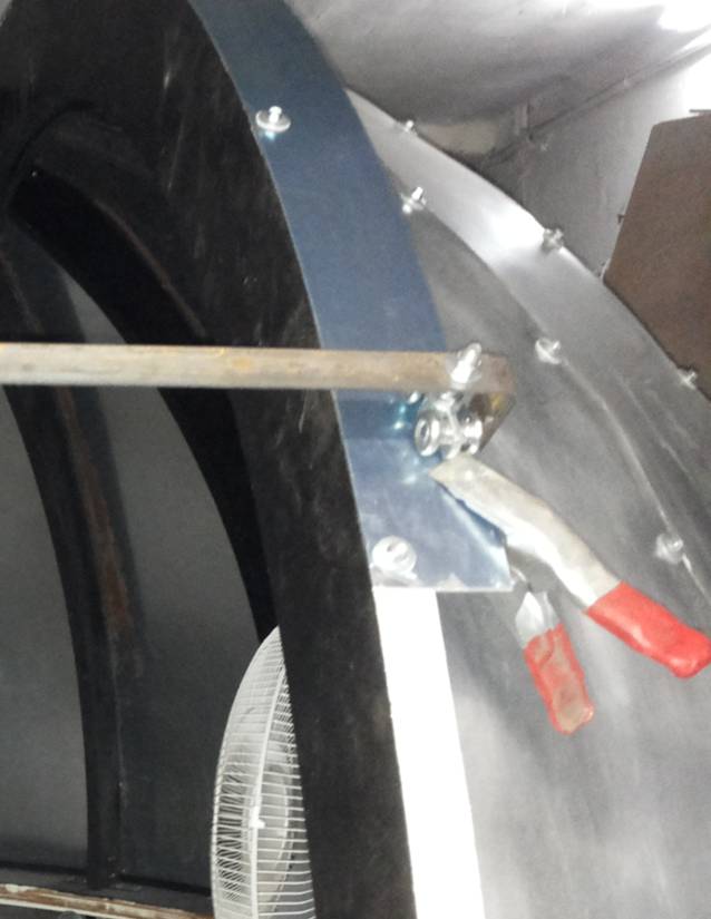
The outside overhang of the slider strip provided a guide for three sets of twin four wheel castor arrays to glide over. Each set of two castor rollers sandwiched the edge of the slider strip between them above and below, thus allowing gliding of the hatch over the guide strip while making sure it remains firmly anchored to the dome preventing undue upward or sideways movement.
Use of a test runner made from a length of flat bar with the twin castor arrays bolted to both ends provided a very useful gauge on which to base the measurements of the final frame for the main hatch.
… the main hatch frame
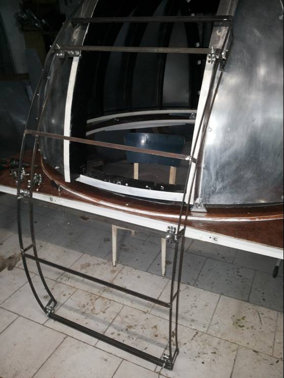
The sliding shutter closing the viewing window, that I call the main hatch was constructed from part of a single galvanized sheet of metal that was bent over to match the curvature of the dome and mounted on a steel frame built from flat bars and angles welded together.
The steel frame was built first. I started by making the side cover frames that would extend downwards from the horizontally placed shutter to bridge the gap reaching to just above the dome flanks. Two lengths of 15 x 4 mm flat were curved sideways along their length. The bending was done cold and the bending jig once again came useful. Their curve was designed to match that of the dome at the level of the window and they were made identical by keeping them clamped together during the shaping process by vice grip wrenches.


These pair of twin metal double arches were next welded to form a pair of closed arched frames that would eventually be covered on the outside by galvanized metal cladding to form the hanging sides of the arched main hatch. The side arched frames were reinforced on the inside by five flat bar struts welded to their inner surface.
The two side frames were next joined together by seven horizontally placed steel sections, using angle bars at the front and back and and flat bars in between. The castor rollers were fitted to the first, third and fifth flat bar from the front, the first flat bar being welded just adjacent to the front angle bar. These horizontal sections were aligned at right angles to the vertical struts of the side frames.